This is a merged information page for Item #4064.
View normal product page.
Pololu item #:
4064
Brand:
Pololu
Status:
Active and Preferred

This small lidar-based distance sensor reports the distance of objects up to about 50 cm (20″) away with a pulsed signal similar to a hobby servo control signal. A digital microcontroller pin can be used to time the length of each high pulse, which encodes the measured distance. The sensor works over an input voltage range of 3.0 V to 5.5 V, and the 0.1″ pin spacing makes it easy to use with standard solderless breadboards and 0.1″ perfboards.
Note: The maximum range of 50 cm is only achievable for high-reflectance objects in good ambient conditions. Lower-reflectivity targets or poor ambient conditions will reduce the maximum range.
Alternatives available with variations in these parameter(s): maximum range Select variant…
 Compare all products in Pololu Digital Distance Sensors.
|
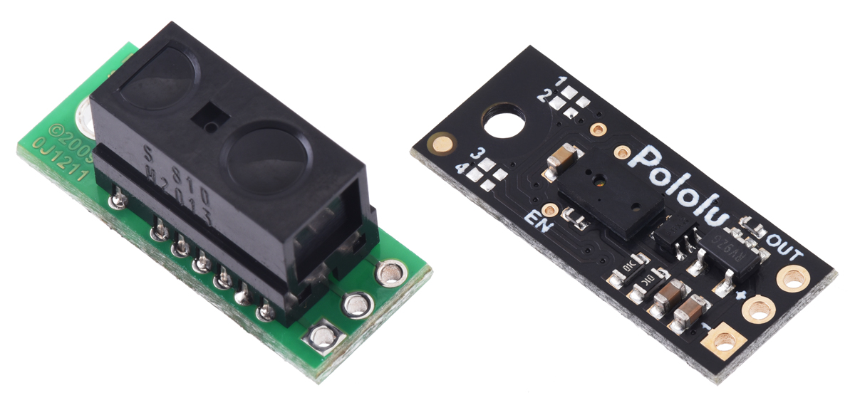
Pololu Distance Sensor with Pulse Width Output, 50cm Max. |
|---|
 |
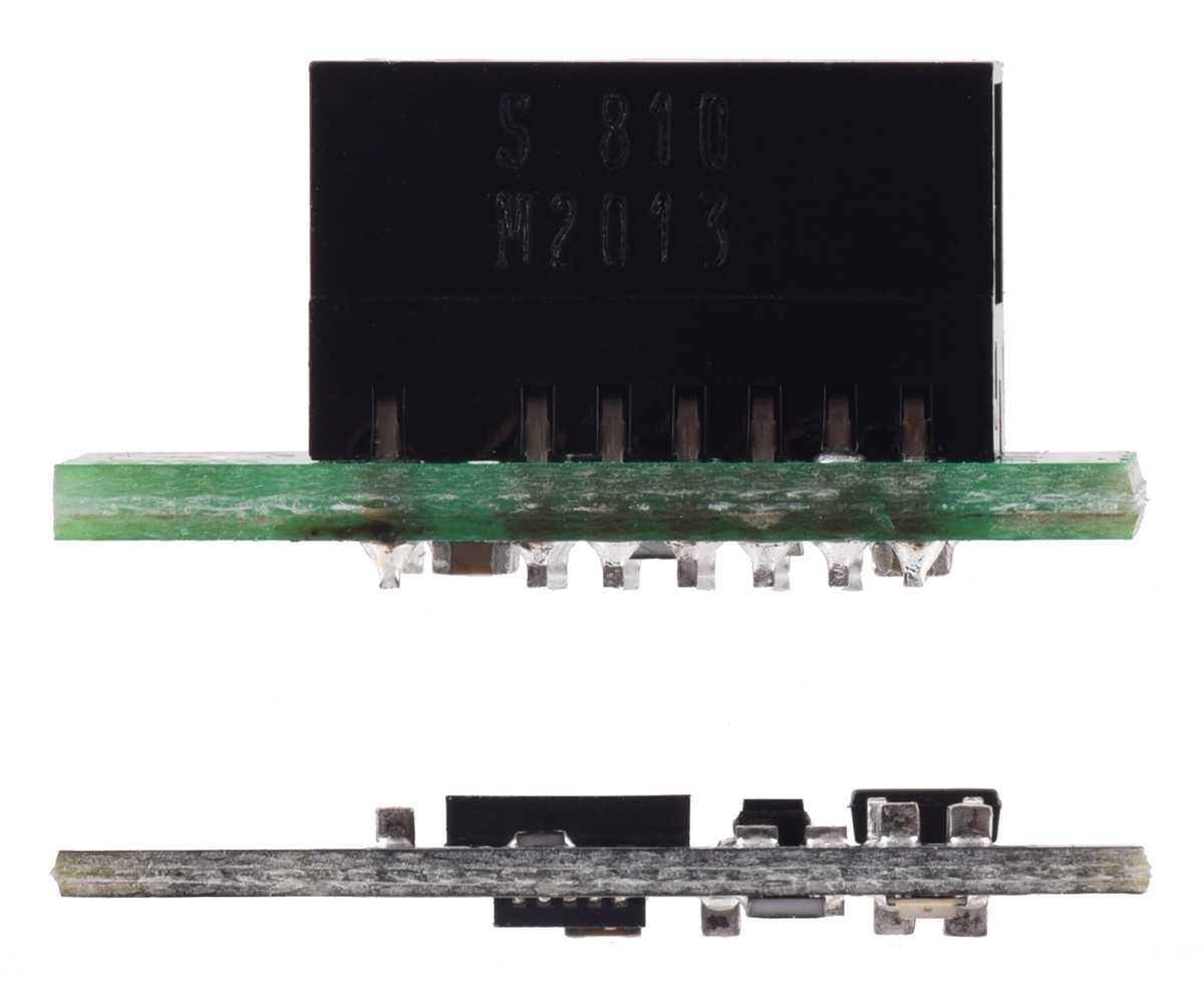
Pololu Distance Sensor with Pulse Width Output, 50cm Max, bottom view. |
|---|
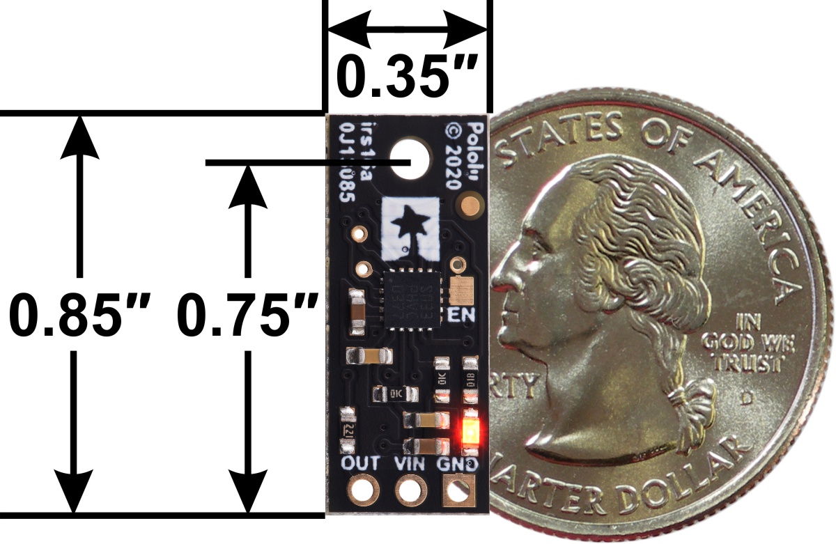 |
Pololu Distance Sensor with Pulse Width Output, 50cm Max, bottom view with dimensions. |
|---|
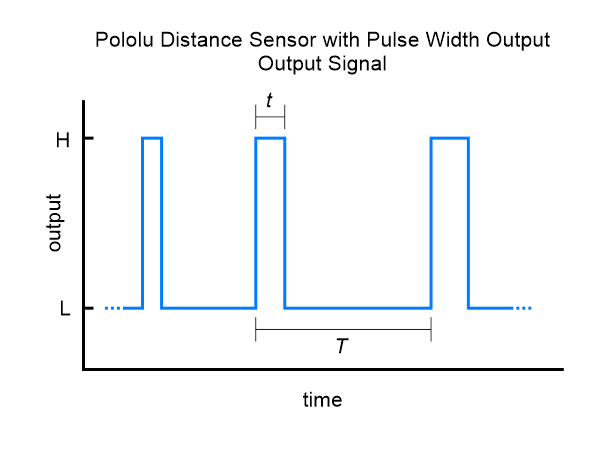 |
Pololu Distance Sensor with Pulse Width Output signal diagram. |
|---|
 |
Graph of measured vs. actual distances for five Pololu Distance Sensors with Pulse Width Output, 50cm Max. |
|---|
 |
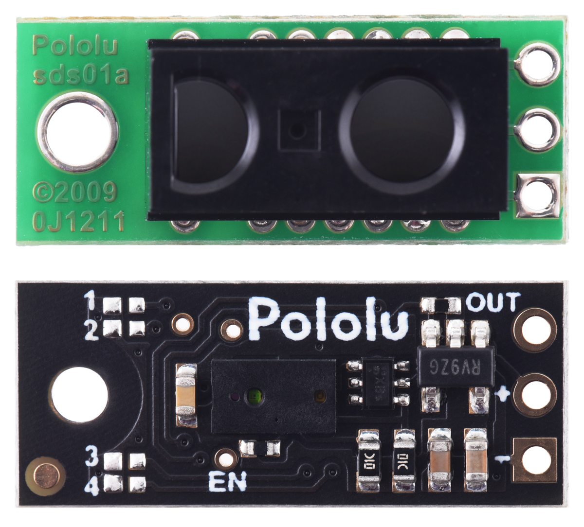
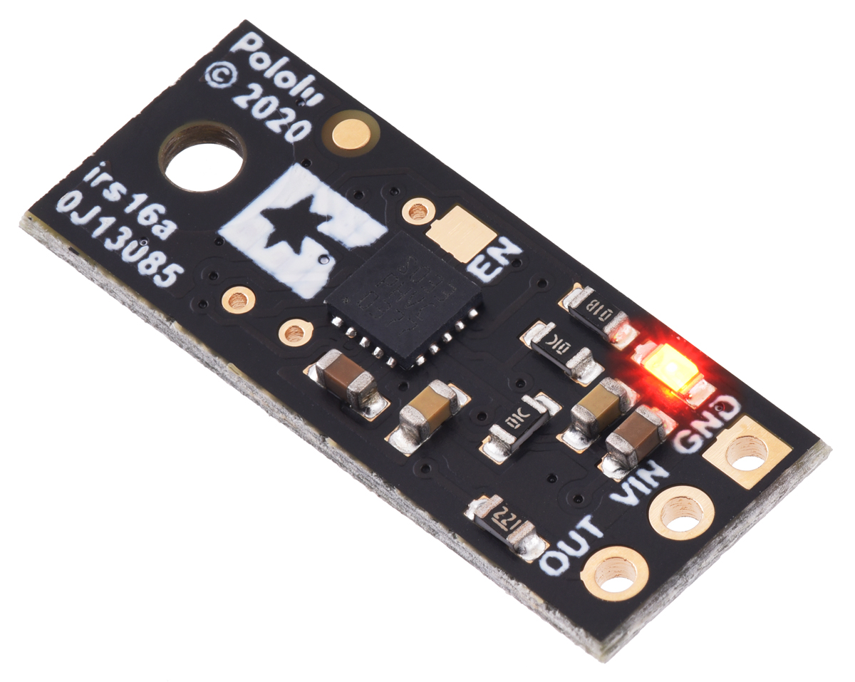
Pololu Distance Sensor with Pulse Width Output, 50cm Max, top view. |
|---|
 |
Pololu Distance Sensor with Pulse Width Output, 50cm Max, bottom view. |
|---|
 |
Pololu Distance Sensor with Pulse Width Output, 50cm Max, top view with labeled pinout. |
|---|
 |
A camera with no IR filter shows the infrared light emitted by a Pololu Digital Distance Sensor. |
|---|
 |
Standard packaging for the Pololu Distance Sensor with Pulse Width Output, 50cm Max. |
|---|
This compact sensor makes it possible to measure the distance of objects up to about 50 cm (20″) away using a simple digital pulse width interface (similar to a hobby servo control signal). It uses a short-range lidar module to precisely measure how long it takes for emitted pulses of infrared, eye-safe laser light to reach the nearest object and be reflected back, allowing for 3 mm resolution. As long as the sensor is enabled, it takes continuous distance measurements and encodes the ranges as the widths of high pulses, which can then be timed by a microcontroller using a single digital input.
|
|
A camera with no IR filter shows the infrared light emitted by a Pololu Digital Distance Sensor. |
|---|
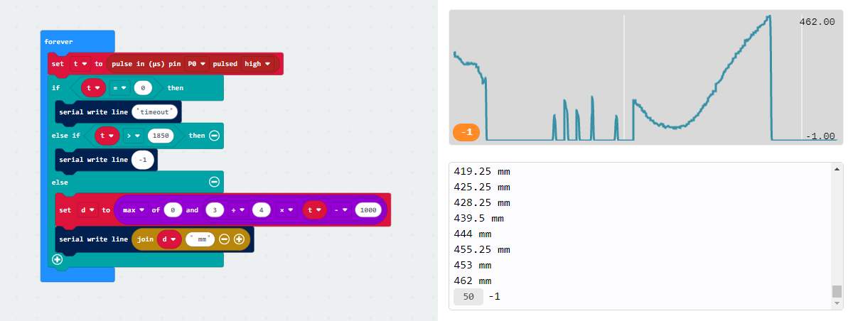
The relationship between measured distance d (in mm) and pulse width t (in µs) is as follows:
``d = (3 text( mm)) / (4 text( µs)) * (t – 1000 text( µs))``
``t = 1000 text( µs) + (4 text( µs)) / (3 text( mm)) * d ``
The timing uncertainty is approximately ±5%. As objects approach the sensor, the output pulse width will approach 1.0 ms, while an object detected at 50 cm will produce a 1.667 ms pulse width. The sensor uses a pulse width of 2.0 ms to indicate no detection. The pulse period T ranges from around 9 ms to 20 ms, depending on the proximity of the detected object.
The maximum detection range depends on object reflectivity and ambient lighting conditions. In our tests, the sensor was able to reliably detect a white sheet of paper out to around 50 cm away, and it could reliably detect a hand out to around 30 cm away. The following graph shows the measured distances of five units versus their actual distances from a white paper target at several different ranges:
|
Please note that while this sensor can detect objects to within about 5 mm of the sensor face, the effective minimum distance it can measure is around 1 cm, so objects closer than 1 cm might result in an inaccurate measurement.
Incorrect distance readings on some units produced before 30 January 2024: A small percentage of units with the original irs16a firmware could report distance readings offset by approximately 25 cm when operating in modes with a maximum range of 20 cm or more. All units shipped from Pololu on or after 30 January 2024 have a newer firmware version with this issue corrected. For more information, see the firmware history section at the bottom of this page.
|
|
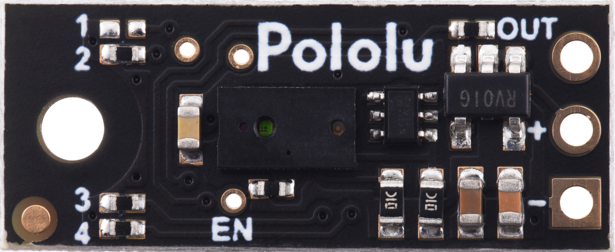
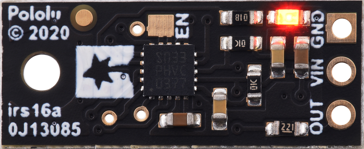
Three connections are necessary to use this module: VIN, GND, and OUT. These pins are accessible through a row of 0.1″-pitch through holes, which work with standard 0.1″ (2.54 mm) male headers and 0.1″ female headers (available separately). The VIN pin should be connected to a 3 V to 5.5 V source, and GND should be connected to 0 volts. The sensor outputs its digital pulses on the OUT pin. The low level of the pulses is 0 V, and the high level is VIN. A red LED on the back side of the board also lights whenever an object is detected (the closer the object, the brighter the LED).
|
|
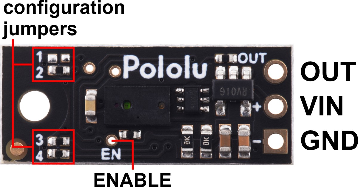
The board has an optional ENABLE pin that can be driven low to put it into a low-power state that consumes approximately 0.4 mA. This pin can be accessed through a via or its neighboring surface-mount pad on the back side labeled “EN” on the silkscreen. The ENABLE pin is pulled up to VIN, enabling the sensor by default.
The board has one mounting hole intended for use with #2 or M2 screws.
This is a simple Arduino sketch that reads the output of the Pololu Distance Sensor with Pulse Width Output, 50cm Max and displays the measured distance in millimeters.
// Example Arduino program for reading the Pololu Distance Sensor with Pulse Width Output, 50cm Max

// Change this to match the Arduino pin connected to the sensor's OUT pin.
const uint8_t sensorPin = 2;

void setup()
{
  Serial.begin(115200);
}

void loop()
{
  int16_t t = pulseIn(sensorPin, HIGH);

  if (t == 0)
  {
    // pulseIn() did not detect the start of a pulse within 1 second.
    Serial.println("timeout");
  }
  else if (t > 1850)
  {
    // No detection.
    Serial.println(-1);
  }
  else
  {
    // Valid pulse width reading. Convert pulse width in microseconds to distance in millimeters.
    int16_t d = (t - 1000) * 3 / 4;

    // Limit minimum distance to 0.
    if (d < 0) { d = 0; }

    Serial.print(d);
    Serial.println(" mm");
  }
}
We have also created a MakeCode example program for the BBC micro:bit single-board computer that demonstrates how to read and convert the output of the Pololu Distance Sensor with Pulse Width Output, 50cm Max. The program’s output can be viewed in the MakeCode device console, which also plots the readings on a graph. You can open the program in the micro:bit MakeCode editor by clicking this link or the picture below.
The board features four surface-mount configuration jumpers that determine its operation mode. Different versions of the Pololu Digital Distance Sensors ship with the appropriate jumpers pre-populated with 0 Ω resistors. These resistors can be desoldered from the populated spots or solder bridges can be added across the unpopulated spots to convert one sensor version into another. This sensor can be converted into any other irs16a version as listed in the following table. (For more information about how the different output types work, see the product pages for representative versions.)
| Item # | Description | Maximum range* |
Hysteresis | Resolution | Minimum update rate |
Jumper settings (4321) |
|---|---|---|---|---|---|---|
| #4050 | Digital output, 5cm | 5 cm | 16 mm | - | 145 Hz | 0000 |
| Digital output, 5cm (high sensitivity) | 5 cm | 16 mm | - | 65 Hz | 0001 | |
| #4052 | Digital output, 10cm | 10 cm | 20 mm | - | 115 Hz | 0010 |
| Digital output, 10cm (high sensitivity) | 10 cm | 20 mm | - | 30 Hz | 0011 | |
| #4054 | Digital output, 15cm | 15 cm | 24 mm | - | 95 Hz | 0100 |
| Digital output, 15cm (high sensitivity) | 15 cm | 24 mm | - | 15 Hz | 0101 | |
| Digital output, 20cm | 20 cm | 28 mm | - | 70 Hz | 0110 | |
| Digital output, 20cm (high sensitivity) | 20 cm | 28 mm | - | 15 Hz | 0111 | |
| Digital output, 30cm | 30 cm | 36 mm | - | 37 Hz | 1000 | |
| Digital output, 30cm (high sensitivity) | 30 cm | 36 mm | - | 15 Hz | 1001 | |
| Digital output, any detect | ~50 cm | - | - | 50 Hz | 1010 | |
| Digital output, any detect | ~100 cm | - | - | 15 Hz | 1011 | |
| Pulse width output, 15cm max | ~15 cm | - | 1 mm (= 4 µs) |
145 Hz (190 Hz max) |
1100 | |
| Pulse width output, 35cm max | ~35 cm | - | 2 mm (= 4 µs) |
95 Hz (165 Hz max) |
1101 | |
| #4064 | Pulse width output, 50cm max | ~50 cm | - | 3 mm (= 4 µs) |
50 Hz (110 Hz max) |
1110 |
| Pulse width output, 100cm max | ~100 cm | - | 3 mm (= 4 µs) |
15 Hz (110 Hz max) |
1111 |
* Effective range depends on object reflectivity and ambient lighting conditions.
Item numbers in this table indicate versions that we offer for sale as standard products, but we can manufacture the other versions on demand (or even make sensors with custom firmware for you). If you are interested in customization, please contact us.
We have several different versions of Pololu Digital Distance Sensors, all with the same dimensions and pinout:
| Digital output (does not provide distance measurement) |
||||||
| Sensor | Maximum range1 |
Minimum range |
Minimum update rate |
Jumper settings (4321) |
PCB ID | Price |
|---|---|---|---|---|---|---|
| #4050: Digital output, 5cm | 5 cm | < 5 mm | 145 Hz | 0000 | irs16a | $14.95 |
| #4052: Digital output, 10cm | 10 cm | < 5 mm | 115 Hz | 0010 | ||
| #4054: Digital output, 15cm | 15 cm | < 5 mm | 95 Hz | 0100 | ||
| #4066: Digital output, 25cm | 25 cm | < 1 mm | 100 Hz | 0000 | irs17a | $19.95 |
| #4067: Digital output, 50cm | 50 cm | < 1 mm | 100 Hz | 0001 | ||
| #4069: Digital output, 100cm | 100 cm | < 1 mm | 100 Hz | 0011 | ||
| #4077: Digital output, 200cm | 200 cm | < 1 mm | 30 Hz | 1011 | ||
| Pulse width output (provides distance measurement) |
|||||||
| Sensor | Maximum range1 |
Minimum range2 |
Resolution | Minimum update rate |
Jumper settings (4321) |
PCB ID | Price |
|---|---|---|---|---|---|---|---|
| #4064: Pulse width output, 50cm max | ~50 cm | 1 cm | 3 mm | 50 Hz | 1110 | irs16a | $14.95 |
| #4071: Pulse width output, 130cm max | ~130 cm | 4 cm | 1 mm | 100 Hz | 0101 | irs17a | $19.95 |
| #4079: Pulse width output, 300cm max | ~300 cm | 4 cm | 2 mm | 30 Hz | 1101 | ||
1 Effective range depends on object reflectivity and ambient lighting conditions.
2 Objects closer than the minimum distance can still be detected, but the measured distance might be inaccurate. The minimum detection range is < 5 mm for irs16a boards and < 1 mm for irs17a boards.
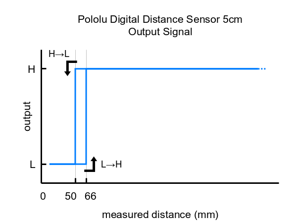
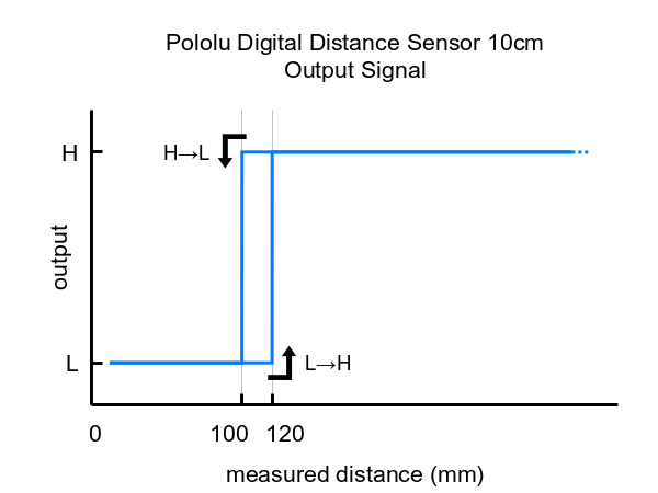
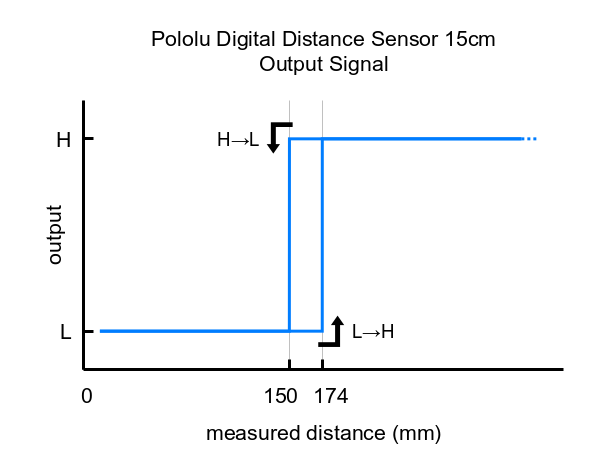
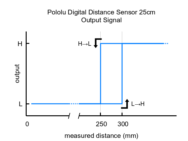
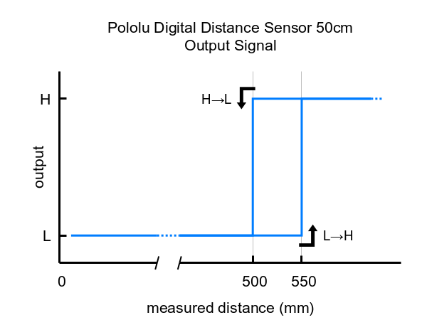
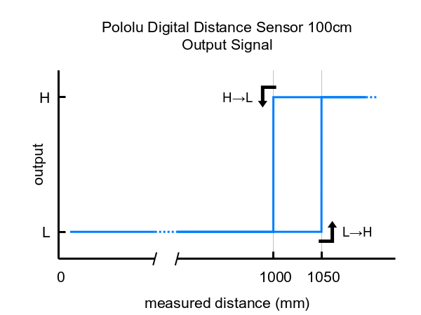
These are the output graphs for the digital output versions that just report if an object is in their detection range:
|
|
|
|||
|
|
|
|||
|
The output graph is a bit different for the versions that use a pulse width to encode the measured distance. The output for these versions is similar to hobby servo control signals and is shown below as a function of time:
|
These Pololu Digital Distance Sensors have the same form factor and pinout as our carrier boards for the Sharp/Socle GP2Y0D8x digital distance sensors. They are available in the same 5 cm, 10 cm, and 15 cm ranges, in addition to longer ranges of up to several meters. This means they can be used as replacements for these older modules, which are based on sensors from Sharp/Socle that are no longer in production, and the longer-range versions can serve as upgrades that provide enhanced detection and measurement capabilities. The sensors on these newer units are much thinner than the Sharp modules, so the zero-range point is approximately 7 mm closer to the PCB, and the beam angle of the newer units is wider. The pictures below show side-by-side comparisons of the two:
|
|
|
The Pololu Digital Distance Sensors (irs16a and irs17a) use a small integrated microcontroller to operate the distance sensor, drive the OUT pin, and control the on-board LED. There have been several different versions of the firmware for this microcontroller:
If you have an affected irs16a unit with firmware version 2 and you would like a replacement, please contact us.
When you apply power to the board or make it reset by any other means, the microcontroller transmits a signal with the firmware version on the via marked in the picture below.
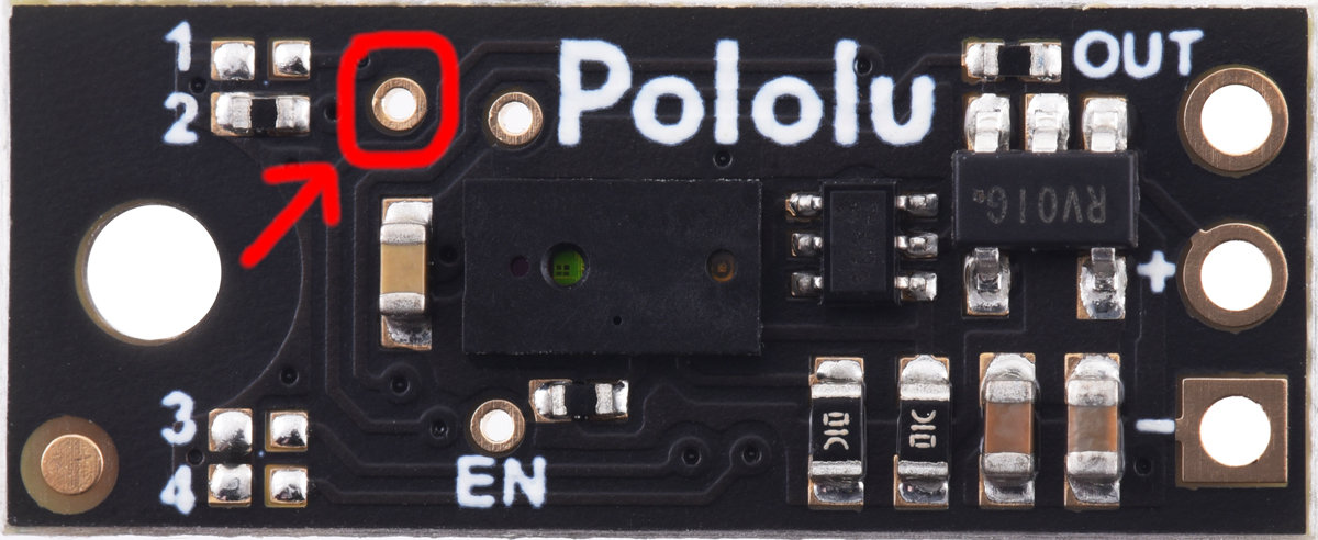 |
The via that outputs firmware version information at startup on a Pololu Digital Distance Sensor. |
|---|
To see the signal, you can probe the via with an oscilloscope. Configure it to trigger on a rising edge with a threshold around 1 V to 2 V and to capture data for at least 1 ms after the trigger. Then apply power to the distance sensor.
Each bit in the signal is transmitted as a high pulse. A 1 µs pulse indicates a 0, while a 3 µs pulse indicates a 1. The first two bits are 1 and 0, and they are followed by an 8-bit firmware version number, most significant bit first. The signal from a board running firmware version 4 looks like this:
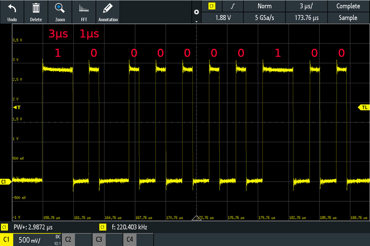 |
Version signal from a Pololu Digital Distance Sensor running firmware version 4 (100 in binary). |
|---|
| Size: | 0.85″ × 0.35″ × 0.122″ |
|---|---|
| Weight: | 0.4 g |
| Resolution: | 3 mm |
|---|---|
| Maximum range: | 50 cm1 |
| Sampling rate: | 50 Hz2 |
| Minimum operating voltage: | 3.0 V |
| Maximum operating voltage: | 5.5 V |
| Supply current: | 30 mA3 |
| Output type: | digital pulse width |
| PCB dev codes: | irs16a |
|---|---|
| Other PCB markings: | 0J13085 |
This DXF drawing shows the locations of all of the board’s holes.
No FAQs available.
In many applications ranging from robotics to industrial automation, it is useful to quickly detect the presence of objects within a certain...